[ Cet article est disponible en Français / This article is available in French ]
As you can see on my other article, I am redoing a Standing Arcades. But I would like to put RGB buttons, that is to say buttons that change color depending on the games, the emulators…
The downside is that the RGB buttons are expensive, very expensive. On the Smallcab website the RGB button is at € 9.90, while a standard luminous button is at € 1.98, or € 1.60 on Amazon. On my Arcade, there are 27 buttons, which makes € 270 if I buy them from Smallcab.
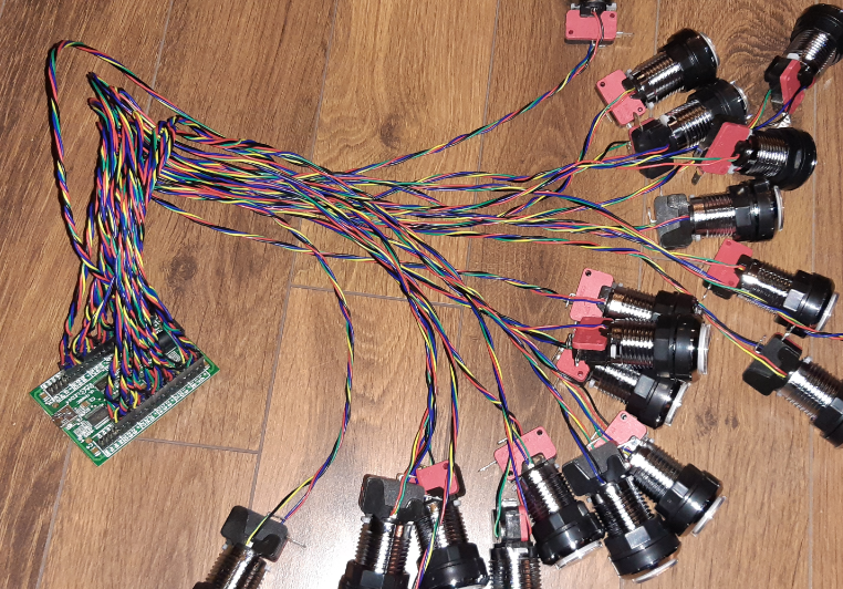
I’m going to show you how to transform a standard button into an RGB button at a minimum cost. RGB buttons can be connected to LED controllers, such as a PACLED 64 USB (Smallcab.net or Ultimarc.com) or I-PAC Ultimate I/O (Ultimarc.com). Then applications like ledblinky can control the LEDs according to events, all the good FrontEnd emulators support ledblinky.
List of necessary equipment :
4-pin RGB LED Anode(Amazon : 13€ for 100 Leds)
Standard illuminated buttons (Smallcab or Amazon:16€ for 10 buttons)
Dupont female connectors (Amazon : clamp+connectors+1x4P Connectors Dupont female 21€ ouconnectors only if you already have the clamp)
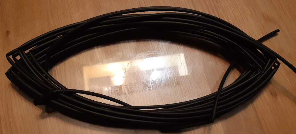
Heat-shrinkable sleeve (Conrad.fr : 0€37/m or 3€70 for 10m)
Wiring wire 0.20 mm² (Conrad.fr : 50m noir 5€77)
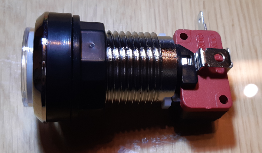
1 – Dismount the button completely
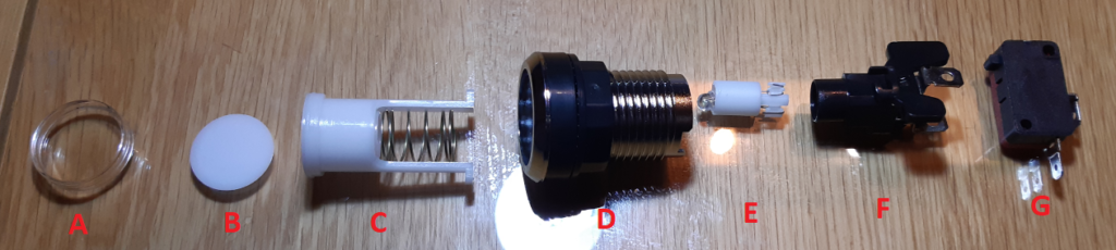
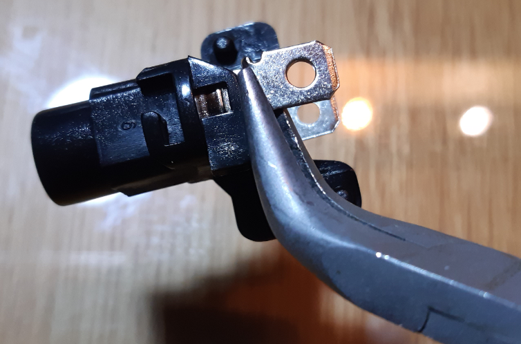
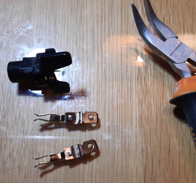
2 – Remove the bulb holder [F] by removing the 2 connectors
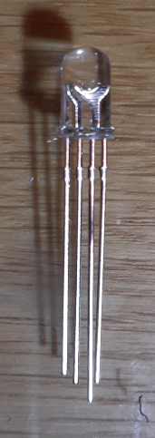
3 – Soldering of the RGB LED
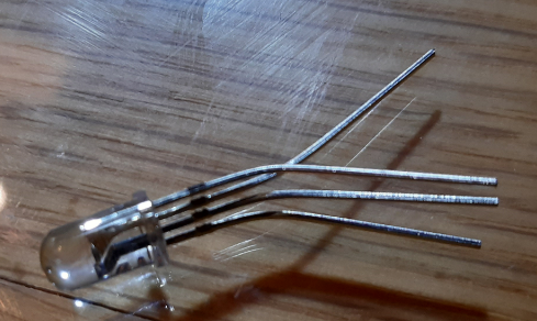
- The longest leg of the LED is +.
- Slightly bend the 3 shortest legs, this will identify the leg (+) and the other 3 legs (Red, Green and Blue)
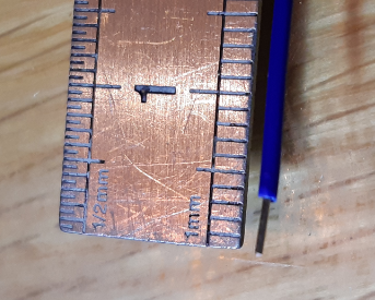
- The legs are slightly too long, remove 5-8mm on each leg.
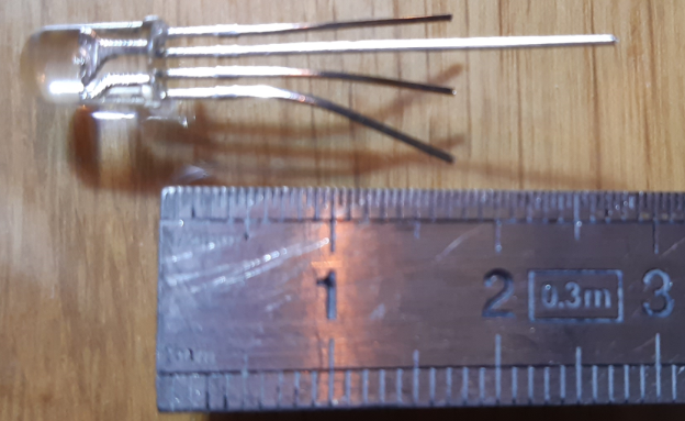
- Legs should measure approximately 20mm
- In the photos, the 3 RGB legs have been cut
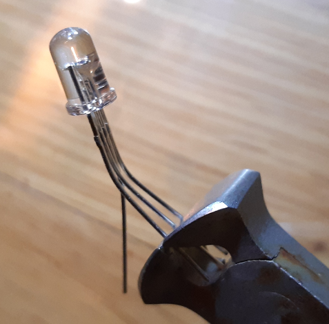
- It is necessary to solder the 4 legs of the RGB LED on 4 wires of about 40cm.
- The most important is to locate the wire which on the + of the led, for the others it is not important. You don’t have to respect the colors at the moment.
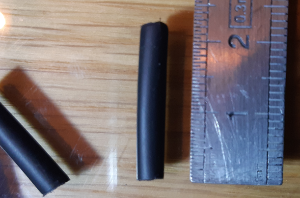
- Cut 4 pieces of thermo sheath of about 20 -22 mm, adapt according to the length of the wire to be protected.
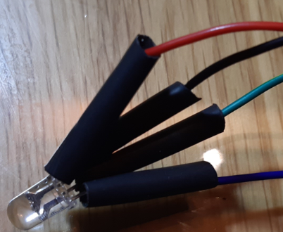
- Put the sheaths on the wires, closest to the led
- Heat the sheath with a lighter or with a match.
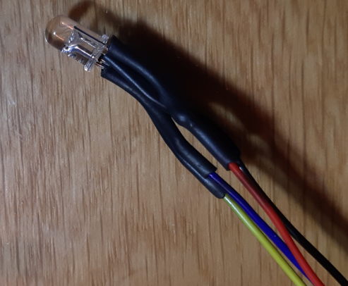
4 – Pass the wires through the plastic support [F]
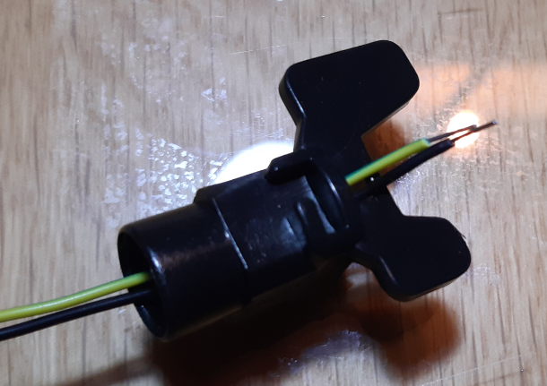
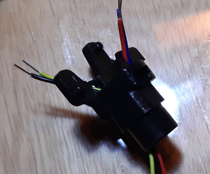
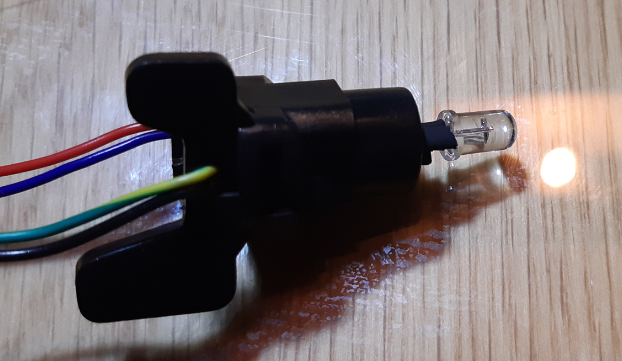
- Pass 2 wires through each opening of the black plastic support.
- Make sure that the LED is pushed in, it should protrude as little as possible.
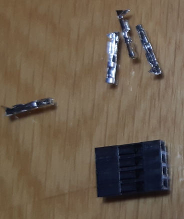
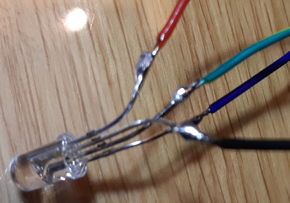
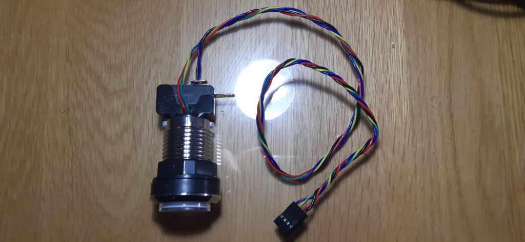
5 – Add the connector 4Pins
- Strip the 4 wires on 3 mm
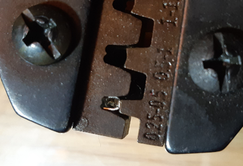
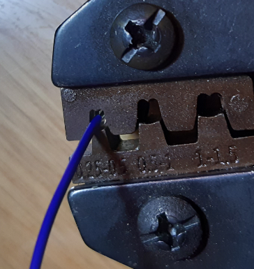
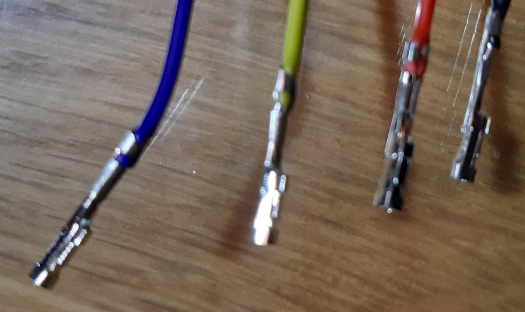
- Attach a metal connector to each end of the wire with the crimp tool.
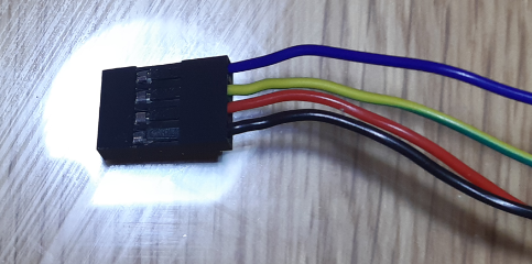
- Attention, check the order of the wires before inserting them into the black 4Pins connector.
- The correct order is: (+) (RED) (GREEN) (BLUE)
- In the “soldering” section, I wrote that it is not necessary to match the color of the wires with the color of the LED, what is important is to put the metal connectors in the correct order in the 4Pins (black plastic connector)
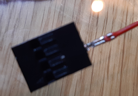
- You must obligatorily test the color, to know if the wire corresponds to the RED, GREEN or BLUE color
6 – Diffuse the LED light well
Some LEDs do not diffuse light evenly across the button. this translates into a bright halo, which is not very pretty. To smooth the LED light, you can use a layer. I add 8 layers of layer, but you can put less it depends on your LEDs.
- Recover the small plastic capsule [B] which is inside the button (see step 1)
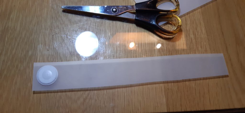
- Cut a layer strip, the width should be slightly larger than the button.
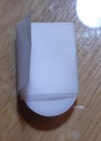
- Cut out the layer using the capsule as a template
- The layer should be slightly smaller than the template
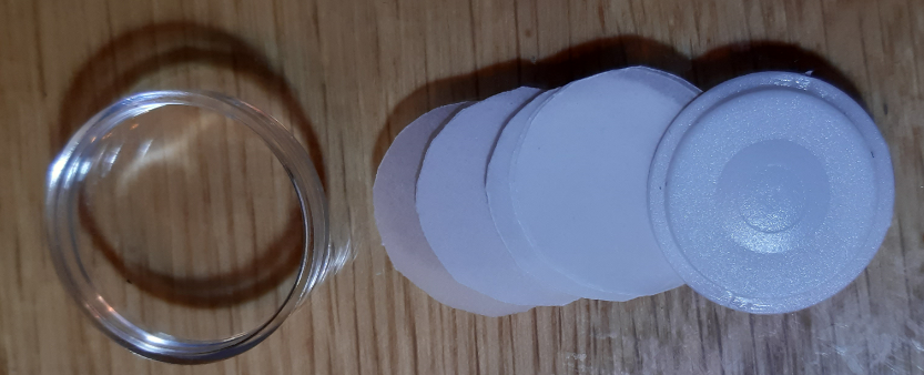
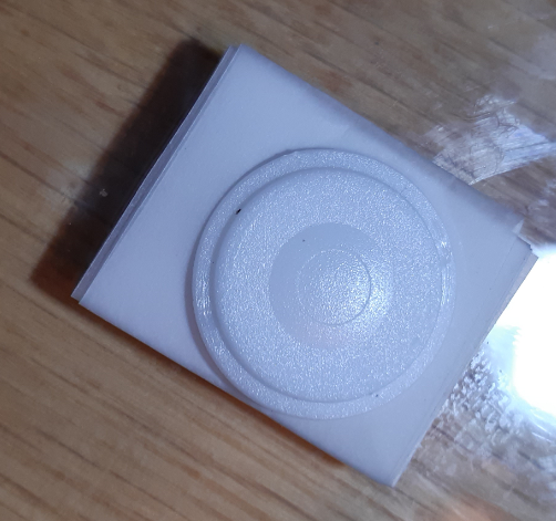
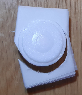
- Replace the capsule [B] with the layers above the button [A]
- The layers are between the top of the button [A] and the capsule [B]
7 – Put it all together
 (2 votes, moyenne: 5.00 sur 5)
2 thoughts on “Transformation (Build) of a normal light Illuminated Button into RGB Button”
C’est un sacré boulot pour faire ça, mais le résultat est là !